Experimentation
The main phases were:
- design elaboration supported by computers and IT;
- three-dimensional virtual verification of the design idea;
- elaboration of mathematical models to interface with the machine tools or rapid prototyping machinery;
- automatic creation of the physical models functional to the artisan building of gypsum moulds;
- automatic creation of gypsum moulds, after construction of semi-finished blocks with a simple geometric form.
Case studies
1. Symmetry and geometric volumes
In this case study rapid prototyping techniques2 were utilised to create a model that faithfully matched the design.
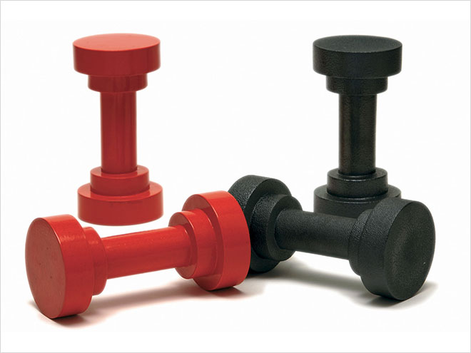
3 kg3
3 Kg a gym dumbbell, is a formally simple yet also a complex object: in fact, its pure geometric forms do not allow for any margin of error during construction. It also has strong constructive symmetry and a very rigid geometric composition. It was decided to use a technique called casting to produce this hollow object, with a hole that can be closed on one of its bases, to be filled with sand or lead pellets, in order to vary its weight and thus the magnitude of the force to be applied during physical exercise.
The first sketches were followed by the geometric elaboration of the forms using a computer and special three-dimensional virtual modelling software.
A Rhinoceros4 type of program was used since it can perceive the object in its entirety, observing it from different viewpoints, checking in detail the virtual external and internal surfaces. The correct proportions and measurements can be analysed and formally checked by a computer starting from two-dimensional drawings up to the virtual 3D construction of the designed object.
The tactile verification of what is simulated on the computer is a fundamental step in the design process. In this case, the production of study maquettes was replaced by the construction of a functional model to be used afterward to produce the gypsum mould.
Given the object’s symmetry, it was determined that the best production procedure would be to divide it into two equal parts. This division made it possible to use the large base as a support surface, thus reducing the construction of supports to a minimum5. This modus operandi was also determined by the fact that the best direction to apply slicing6 facilitated the construction of 3 Kg in two parts. Afterwards, the two elements, made out of ABS7, were glued together.
Production time amounted to 36 machine hours for rapid prototyping, using 500 cm3 of ABS for the model and 20 cm3 of soluble resin for the supports. The prototyping machines can run continuously and do not require constant monitoring by a technician. Thus, production time can be optimised and operations planned based on a 24/7 schedule, instead of on the usual work hours.
The technology used to make 3 Kg involved the use of an FDM (Fused Deposition Modelling) machine with the following building phases:
1. fusion of the material through the system head;
2. path formation (road);
3. variation in deposit thickness, depending on the material used: 0.125 mm, 0.178 mm, 0.254 mm, 0.305 mm, 0.330 mm (slicing);
4. prototype building.
The prototype built using the FDM does not require any post-treatment. The process also has the advantage of being “clean” as far as environmental impact is concerned. In general, the materials used have a low fusion point and thus the effect on energy consumption is also limited. The material, in the form of a filament, is wound on a coil mounted in the rear of the machine. While being worked, the material is heated to about 270°C so that it is almost a liquid. Then, while the deposition head translates horizontally, the material is extruded and deposited on the previous layer. The system first defines the contour of the section and then its fill-in. The deposition head is equipped with two nozzles that work in an alternating pattern: one deposits the model material and the other the support material, necessary if there are projecting parts, underlying closed cavities, undercuts and holes.
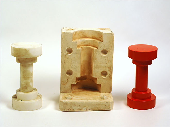
Process phases: from the R.P. model to the product
2. From the file to the mould without intermediary steps
Experimentation with the 3 Kg also focused on verifying another hypothesis8: to build the gypsum mould directly without constructing a physical model of the designed object. To do this high-–speed milling9 was used to create semi-finished cast gypsum blocks using computerised numeric control machine tools10.
The mould’s technical design is created by using subtraction controls between solid figures that can be managed with the software used in 3D design engineering applications. The same three-dimensional image is used to “hollow out” or, even better, to “subtract” from a regular geometric figure, thus determining the dimensional characteristics of the mould.
The mould project file is exported in the .stl format and, once transferred into the computer linked to the machine, manages the mould building process. The file processing program is called Ideas, a software application capable of generating tool paths, after the operator has determined the most suitable mill for the project, establishing the ideal translation speed and the rpm of the spindle11, based on the settings of the cutting characteristics of the material used.
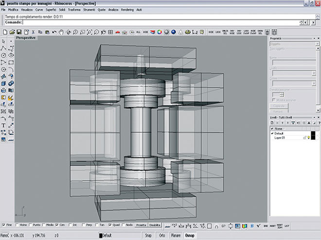
Three-dimensional virtual elaboation of the mould
Digital representation of the mould components
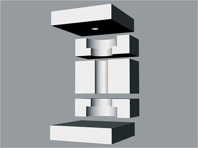
Then, the design activities continue by breaking the mould down into its constituent parts. Thanks to the symmetrical shape of the object it was easer to break down the virtual mould into its various parts. First, the two bases, consisting of simple parallelepipeds, were identified. The upper base contains the truncated conic hole of the riser12 to cast the barbottina13 and then empty the mould. The central part of the mould was then divided into two parts according to the axis of longitudinal symmetry. This subdivision into two shells should be suitable for casting, but because it was necessary to create perfectly defined angles and corners, each semi-mould had to be divided into three parts, based on the cutting tool path and section.
The identical central parts were hollowed out using a tool with a rounded tip, with translation movements parallel to the longitudinal axis and minimum quantities of material removed with each pass. The four peripheral parts, which are also identical, were made instead using a square-tipped tool to create sharp angles and corners. During the “hollowing out” operations, the blocks were automatically ground to reduce them to the nominal design measurements, also guaranteeing the perfect coplanarity and therefore an efficient seal between the parts produced in this manner.
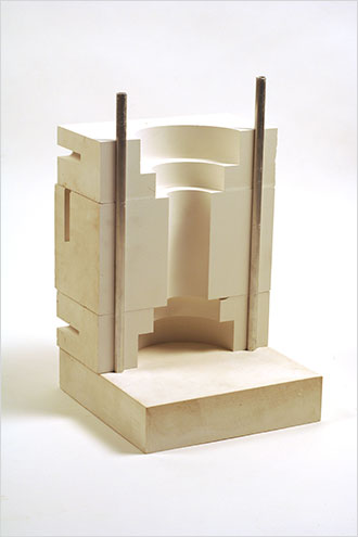
Mould recomposition and assembly of the high-speed milled parts
Thus, gypsum blocks must be made with the dimensions needed to create the individual parts forming the mould. The fluid gypsum is poured into wooden forms lined with smooth laminated material to make detachment easier and create smooth surfaces. The semi-finished blocks are slightly oversized so that they can be ground during the computerised numeric control operation. Milling is carried out on dry blocks that, therefore, when removed from the forms, are allowed to dry for between a few days to several weeks.
The direct transition from the mathematics of the designed object to the construction of the mould significantly reduces the amount of time involved (the high-speed milling operations required 12 machine hours plus 1 hour to define the tool path) and produces perfect forms and dimensions. The process could be even further optimised with an assortment of prefabricated cast gypsum blocks.
Protoypes in enamelled ceramic
3. Beyond the geometry of forms
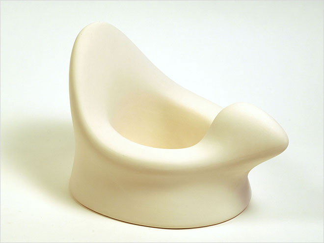
The process to build the rapid prototyping model14 was also verified for the construction of an object with sinuous and rounded shapes: the ironic revisitation in ceramic of a children’s potty.
In this case, the graphic transposition of the design idea was carried out directly on the computer. The object was produced using a virtual modelling program that completes and modifies the three-dimensional modelling by shifting the construction nodes15 of the same object, translating them in virtual space after linking them with the mouse or indicating their X, Y, Z coordinates.
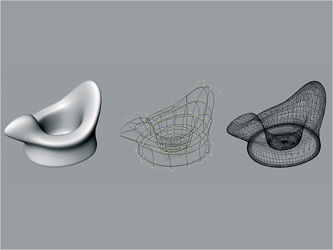
Virtual elaboration of the project
Model in ABS made using the rapid prototyping method
To interface the project with the prototyping machine, the three-dimensional file is exported in the .stl format. For an object with these dimensions (270 x 380 x 260 mm) it was more convenient to break down the prototype into two parts, sectioned from a horizontal plane. This optimised the processing time and the quantity of material used, reducing the construction supports.
The supports, then partially eliminated, were needed to support the projecting parts with an inclination of more than 45°. The image shows the residual supports, made out of dark resin, preserved to keep the central concave part raised with respect to the bottom.
The surface of the ABS, the material used to build the prototype, can be finished by means of brief passes using sandpaper. Thus, it is possible to reduce the “scaling” effect, due to the sequence of deposition layers of the molten material.
The model again becomes a single piece by gluing the parts using a tough adhesive like cyanoacrylic glue. The joint line was finished with an abrasive cloth to remove any excess glue. The prototype is thus ready for the craftsman production of the gypsum mould.
The mould was made in 4 parts (the base, the two sides, the upper part) maintaining a constant thickness around the model. This improves the uniformity of the barbottina drying and, as a consequence, of the thickness of the ceramic product.
The mould is precisely recomposed by using the centering pins and the connections between the pieces.
After casting the barbottina, and waiting the time needed to ensure optimum drying, the piece is removed.
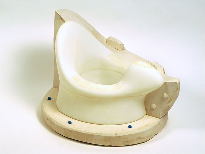
From the model to the handcrafted construction of the gypsum mould
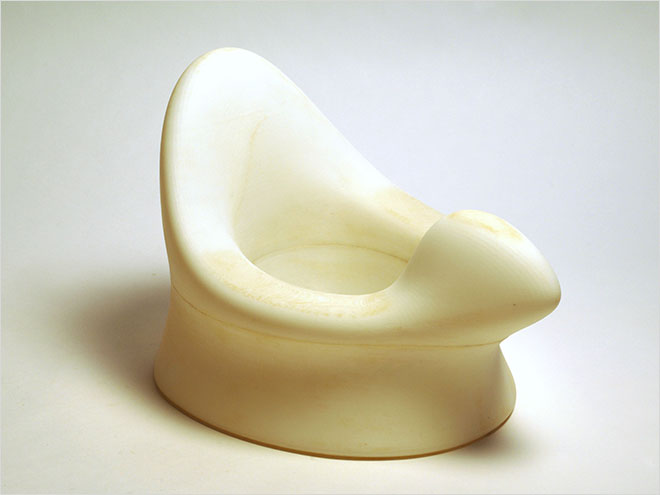
Perfect correspondence between project, model and ceramic product created by casting
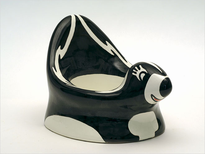
The prototype
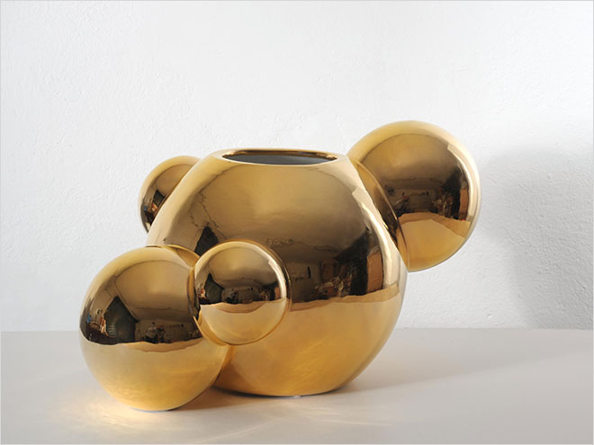
4. Compositional complexity
The process that leads to the craftsman fabrication of a ceramic object by casting with the support of rapid prototyping technology was also experimented starting from a vase design created by the Atelier Mendini16.
The three-dimensional virtual model was developed based on the information indicated in the two-dimensional drawing with the support of a CAD program.
Its analysis confirmed that technology could be used to product the model using automated methods. The direct transition from the mathematical elaborations to construction of the physical model maintains the geometric rigour of the spherical volumes and of the curved lines generated by their intersection.
To optimise the production process, the object was exploded into its elementary geometric elements. The main sphere, forming the body of the vase, was “hollowed out” in the areas in which the “satellite” spheres penetrate into each other.
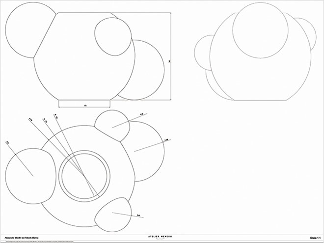
Peoject drawing
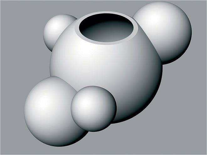
Three-dimensional virtual elaboration
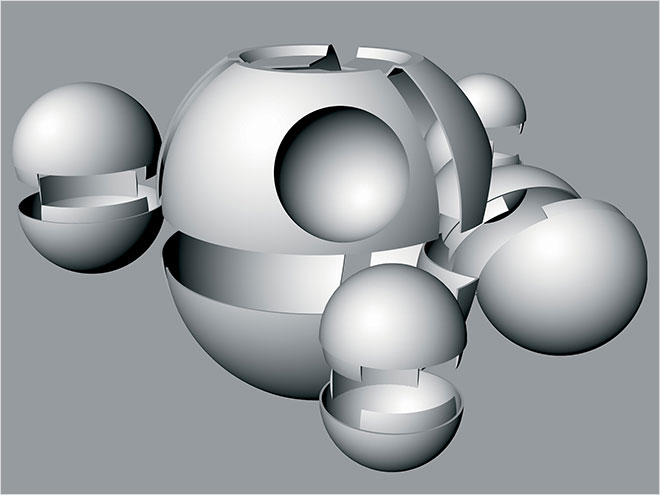
Virtual decomposition of the model to optimise the production phases
Based on how the mould is constructed, it was decided to close the mouth of the vase, slightly under the edge. In this way, the cavity created in the gypsum mould will give the edge a suitable thickness.
The control software of the prototyping machine (Stratasys FDM 3000) was used to identify the cutting lines, generated by secant planes, along which to section the single portions. This operation was necessary to optimise the construction process, obtaining the best relationship with respect to production cost. The object to be prototyped does in fact have a large number of very projecting undercut surfaces. Therefore, the construction of the monolithic prototype would require a large quantity of material for the supports, thus significantly increasing the costs.
The best solution turned out to be that of dividing the four satellite spheres into two equal parts, sectioned by the plane passing through the maximum parallel. The spherical body of the vase was sectioned by planes passing through the meridians, spaced 90° from each other, into 4 sections, divided, in turn, by the median horizontal plane.
Then, the connecting tabs were designed so that the parts would perfectly match during assembly and gluing.
The prototype, with the dimensions 575.5 x 441.6 x 318.6 mm, required about 250 machine hours to construct.
The prototype is then used as a model for the craftsman production of the gypsum mould.
The mould thickness was kept constant, and skilfully so, thus ensuring that the barbottina would solidify uniformly.
Dividing the mould makes it easier to extract the ceramic piece, which has not completely solidified after the first drying phase, thus avoiding breakage or accidental deformations.
The finished product has perfectly regular and defined spherical volumes and lines, generated by their intersection, reduced to precise geometric entities, based on the indications determined from the design documents.
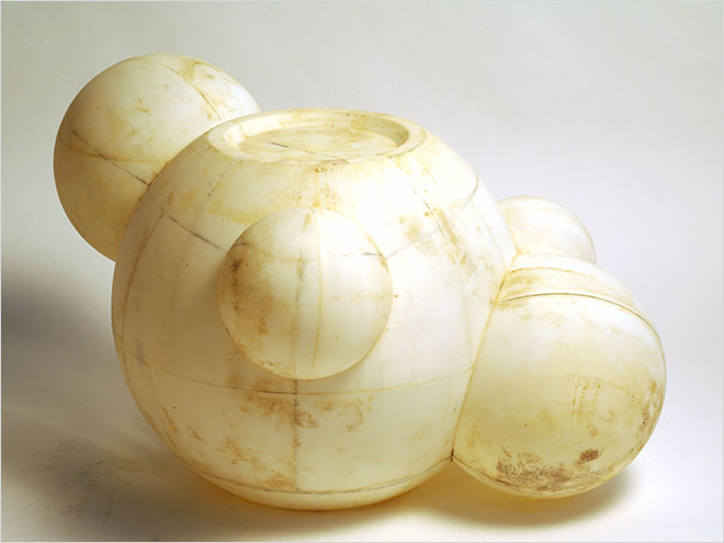
Model in ABS made using the rapid protoyping method
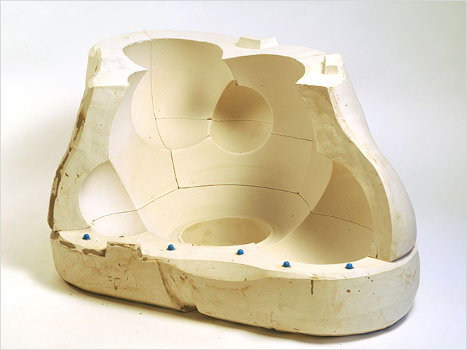
Portion of the gypsum mould for the casting
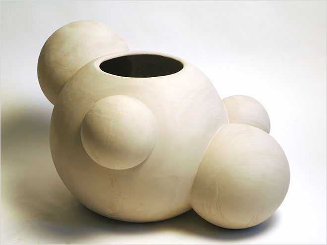
The product extracted from the mould
The prototype
2. Rapid prototyping – RP: set of systems capable of reproducing even formally complex objects using additive techniques that begin from the mathematical characteristics of the objects.
3. Project: 3Kg; designer: Alessandro Biamonti; experimentation: rapid prototyping model building; digital processing: Alessandro Biamonti; prototype construction: Techimold Servizi S.r.l.; mould building, casting, firing: Jorge Hernandez; enamelling: La Nuova Fenice di Barbara Arto.
4. Rhinoceros: three-dimensional modelling program used extensively in architectural engineering and design.
5. Supports: these are necessary if the object has projecting forms with diagonal lines with an angle of more than 45°. Made with fibreglass, they can be eliminated after building.
6. Slicing: scaling the surface of a rapid prototype, following stratification of the building material by horizontal planes with a predetermined thickness.
7. ABS: acrylonitrile butadiene styrene, thermoplastic copolymer.
8. Project: 3Kg; designer: Alessandro Biamonti/Chiara Bevegni; experimentation: gypsum mould building by means of high-speed milling; digital processing: Alessandro Biamonti; construction of semi-finished gypsum objects: Ylli Plaka; prototype construction: Techimold Servizi S.r.l.; casting, firing: Ylli Plaka; enamel, lustre, 2nd/3rd fire: La Nuova Fenice di Barbara Arto.
9. High-–speed milling: mechanical process that utilises the tool’s high rotation speed and rapid movement to remove chips.
10. Computerised numeric control: machines equipped with automated systems that manage the cutting speed, the definition and the path of the tools to optimise the production process.
11. Spindle: mechanical part that transmits the rotary motion.
12. Riser: piece projecting from the upper part of a fusion casting after drawing.
13. Barbottina: binder made by mixing water and clay.
14. Project: Cagarino/Puzzola; designer: Guido Venturini; experimentation: rapid prototyping model building; digital processing: Guido Venturini; prototype construction: Techimold Servizi S.r.l.; mould building, casting, firing: Ylli Plaka; enamel, lustre, 2nd/3rd fire: La Nuova Fenice di Barbara Arto.
15. Node: it is possible to assign a different weight to each node, i.e. a different capacity to drag lines of construction or surfaces with it, in the spatial translations.
16. Project: Tre sfere; designer: Alessandro Mendini; experimentation: rapid prototyping model building; digital processing: Chiara Bevegni; prototype construction: Techimold Servizi S.r.l.; mould building, casting, firing: Ylli Plaka; enamel, lustre, 2nd/3rd fire: La Nuova Fenice di Barbara Arto.